If you’ve ever opened a battery enclosure CAD and thought, “This plate looks fine… but will the far-end cells actually see the same coolant?”, you’re in the right place.
I was reviewing a battery pack where the customer only gave us total heat for the module, not per-cell values. Classic. Instead of waiting for “final” data, I just ran a few quick thermal/CFD cases on the cooling plate to see what actually changes the cell-side temperature spread.
Spoiler:inlet position and flow split mattered more than the fancy channel pattern.
Why simulate cooling at all?
Battery cold plates are flat, look simple, and in drawings they always cool “evenly”. Real life isn’t that kind.
- Cells don’t heat the same.
- Coolant loses temperature as it travels.
- Corners of the plate become lazy zones if you feed water from only one side.
So I wanted to answer a small, practical question:
“If I can only change the inlet/outlet location and the flow rate, can I pull the ΔT down enough without redesigning the whole plate?” That’s something a pack engineer or supplier can actually do mid-project.
Test #1: Single-side inlet vs. diagonal inlet
Setup
Same aluminum cooling plate
Same internal channel
Same total heat load applied on the battery contact surface
Coolant: water-glycol, fixed inlet temp
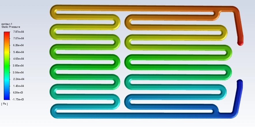
Case A – single-side inlet, outlet on the opposite side
Coolant enters on the short edge, travels all the way, exits on the other edge.
Flow near the inlet was nice and energetic.
Last 20–25% of the plate ran slower.
Surface temperature there was ~1.4–1.6 °C higher.
Case B – diagonal inlet/outlet (inlet bottom-left, outlet top-right)
So the flow “cuts through” the plate.
Flow distribution was more balanced.
Far corner wasn’t starving anymore.
Max surface temperature dropped by about 1 °C compared to Case A.
Not a massive number, but this was a cheap change — just moving ports.
Takeaway: if your plate is wide and you only feed from one side, you will pay for it at the far corner.
Test #2: Small flow bump
Next question: “What if the system pump actually has a bit more to give?”
I reran Case B and increased flow by ~20% (still within what a small pump could do).
- Overall temperatures dropped
- More importantly, the temperature spread between best and worst spots shrank by ~0.5 °C
- Pressure drop went up (of course), but still in a sane range
So even without changing channels, a modest flow bump + better port placement already made the map look “production-friendly”.
Test #3: Pretend the pack got hotter
Because customers love to change requirements, I also threw in a higher heat load — roughly “the same plate, but now it’s fast-charging”.
- Absolute temps went up (no surprise)
- But the pattern stayed the same: the bad area is where flow is weak
Which means if you fix flow early, the plate will scale better when loads increase.
This is useful when the electrical team says “we might go 1.2× later”.
You already know the plate’s behavior.
Final Thoughts
These small “what-if” runs reminded me that in battery cooling, flow is the first-order effect.
Fancy channels help, but if your inlet/outlet placement isn’t feeding the plate evenly, you’re fighting physics with geometry.
If you’re designing or sourcing liquid-cooled plates for EVs, ESS, or power electronics, it’s worth running one quick CFD case early — before the tooling, before the validation.
It saves months later.
That’s how we work at XD Thermal Technology Co., Ltd.
— a full-service supplier of battery cooling plates, serpentine tubes, and housings for EV and energy-storage systems.
We design, simulate, and build thermal hardware that actually scales from prototype to production.